Sophos UTM 9 – HA fails on Hyper-V – Another Master / Slave

So for the past weeks I’m troubleshooting a Sophos UTM 9.4 cluster which won’t come into sync with each other. We’re migrating VM’s from one Hyper-V cluster to a new Hyper-V cluster. On the old cluster we’ve deployed a two node Sophos UTM9 HA cluster.  It’s running fine for years now. During the migration, I’ve shutdown the slave node and migrated it to the new Hyper-V cluster. This all went without issues. However as soon as I booted the slave and it came online, it started complaining about another slave being around and started ‘loosing’ heartbeats:

2017:10:19-21:16:21 fw-1 ha_daemon[28614]: id="38A0" severity="info" sys="System" sub="ha" seq="M: 35 21.210" name="Reading cluster configuration"
2017:10:19-21:16:26 fw-1 ha_daemon[28614]: id="38A0" severity="info" sys="System" sub="ha" seq="M: 36 26.096" name="Set syncing.files for node 2"
2017:10:19-21:16:35 fw-2 ha_daemon[6547]: id="38A1" severity="warn" sys="System" sub="ha" seq="S: 99 35.855" name="Lost heartbeat message from node 1! Expected 724 but got 723"
2017:10:19-21:16:36 fw-1 ha_daemon[28614]: id="38A0" severity="info" sys="System" sub="ha" seq="M: 37 36.251" name="Monitoring interfaces for link beat: eth5 eth4 eth2 eth3 eth6 eth0"
2017:10:19-21:16:36 fw-2 ha_daemon[6547]: id="38A1" severity="warn" sys="System" sub="ha" seq="S: 100 36.856" name="Lost heartbeat message from node 1! Expected 725 but got 724"
2017:10:19-21:16:36 fw-2 ha_daemon[6547]: id="38A1" severity="warn" sys="System" sub="ha" seq="S: 101 36.938" name="Another slave around!"
2017:10:19-21:16:37 fw-2 ha_daemon[6547]: id="38A0" severity="info" sys="System" sub="ha" seq="S: 102 37.048" name="Reading cluster configuration"
2017:10:19-21:16:37 fw-2 ha_daemon[6547]: id="38A0" severity="info" sys="System" sub="ha" seq="S: 103 37.049" name="Starting use of backup interface 'eth0'"
2017:10:19-21:16:37 fw-2 ha_daemon[6547]: id="38A1" severity="warn" sys="System" sub="ha" seq="S: 104 37.857" name="Lost heartbeat message from node 1! Expected 726 but got 725"
2017:10:19-21:16:37 fw-2 ha_daemon[6547]: id="38A1" severity="warn" sys="System" sub="ha" seq="S: 105 37.939" name="Another slave around!"
2017:10:19-21:16:38 fw-2 ha_daemon[6547]: id="38A1" severity="warn" sys="System" sub="ha" seq="S: 106 38.858" name="Lost heartbeat message from node 1! Expected 727 but got 726"
2017:10:19-21:16:39 fw-2 ha_daemon[6547]: id="38A1" severity="warn" sys="System" sub="ha" seq="S: 107 39.859" name="Lost heartbeat message from node 1! Expected 728 but got 727"
2017:10:19-21:16:39 fw-2 ha_daemon[6547]: id="38A1" severity="warn" sys="System" sub="ha" seq="S: 108 39.941" name="Another slave around!"
2017:10:19-21:16:40 fw-2 ha_daemon[6547]: id="38A1" severity="warn" sys="System" sub="ha" seq="S: 109 40.860" name="Lost heartbeat message from node 1! Expected 729 but got 728"
2017:10:19-21:16:41 fw-2 ha_daemon[6547]: id="38A1" severity="warn" sys="System" sub="ha" seq="S: 110 41.861" name="Lost heartbeat message from node 1! Expected 730 but got 729"
2017:10:19-21:16:41 fw-2 ha_daemon[6547]: id="38A1" severity="warn" sys="System" sub="ha" seq="S: 111 41.943" name="Another slave around!"
2017:10:19-21:16:42 fw-2 ha_daemon[6547]: id="38A0" severity="info" sys="System" sub="ha" seq="S: 112 42.088" name="Monitoring interfaces for link beat: eth5 eth4 eth2 eth3 eth6 eth0"
2017:10:19-21:16:42 fw-2 ha_daemon[6547]: id="38A1" severity="warn" sys="System" sub="ha" seq="S: 113 42.863" name="Lost heartbeat message from node 1! Expected 731 but got 730"
2017:10:19-21:16:42 fw-2 ha_daemon[6547]: id="38A1" severity="warn" sys="System" sub="ha" seq="S: 114 42.944" name="Another slave around!"

Ok, so that’s weird. I know there’s lots of networking between the old and new Hyper-V cluster, however that could only explain the ‘lost heartbeat’ messages and not the ‘Another slave around’ message. So what’s going on? In an attempt of resolving the issue right on the spot, I disabled HA on the master which resulted in the slave being factory reset. I thought there might be a flipped bit. But even after rebuilding the cluster and the same issue appeared. Eventually we migrated the slave back to the old Hyper-V cluster. Guess what: problem ‘solved’. Within 5 minutes the slave was in sync with the master and no weird error messages.

I contacted Sophos support and they said it all just should work. To mention: the new Hyper-V cluster has the same OS/Hyper-V version as the old cluster, only newer hardware.

I’ve been debugging this for two weeks and finally a break through: turns out the only other difference between both Hyper-V clusters is the way nic teaming is configured. The old Hyper-V cluster is using LACP, the new cluster Switch independent with Load balancing mode ‘Dynamic’.

Since Sophos HA is using multicast broadcasts those leave one physical nic and since it’s a broadcast the switch backend also sends it to the second team nic. This causes the HA heartbeat message to re-enter the UTM node which send it causing it to think it’s from another Sophos UTM node. Apparently Sophos HA has no way (or it simply doesn’t) to check if the heartbeat message originated from itself.

I confirmed this by deploying a brand new Sophos UTM node to the new Hyper-V cluster. As soon as I turned on HA, it started complaining is was seeing another master. Well that’s odd since this VM was completely isolated in it’s own VLANs.

2017:10:24-13:50:25 fw-testing-1 ha_daemon[4315]: id="38A1" severity="warn" sys="System" sub="ha" seq="M: 49 25.428" name="Another master around!"
2017:10:24-13:50:25 fw-testing-1 ha_daemon[4315]: id="38A0" severity="info" sys="System" sub="ha" seq="M: 50 25.428" name="Enforce MASTER, Resending gratuitous arp"
2017:10:24-13:50:25 fw-testing-1 ha_daemon[4315]: id="38A0" severity="info" sys="System" sub="ha" seq="M: 51 25.428" name="Executing (nowait) /etc/init.d/ha_mode enforce_master"
2017:10:24-13:50:25 fw-testing-1 ha_daemon[4315]: id="38A1" severity="warn" sys="System" sub="ha" seq="M: 52 25.428" name="master_race(): other MASTER with the same solution = 0"
2017:10:24-13:50:25 fw-testing-1 ha_daemon[4315]: id="38A0" severity="info" sys="System" sub="ha" seq="M: 53 25.428" name="Enforce MASTER, Resending gratuitous arp"
2017:10:24-13:50:25 fw-testing-1 ha_daemon[4315]: id="38A0" severity="info" sys="System" sub="ha" seq="M: 54 25.428" name="Executing (nowait) /etc/init.d/ha_mode enforce_master"
2017:10:24-13:50:25 fw-testing-1 ha_mode[6624]: calling enforce_master
2017:10:24-13:50:25 fw-testing-1 ha_mode[6622]: calling enforce_master
2017:10:24-13:50:25 fw-testing-1 ha_mode[6622]: enforce_master: waiting for last ha_mode done
2017:10:24-13:50:25 fw-testing-1 ha_mode[6622]: enforce_master
2017:10:24-13:50:25 fw-testing-1 ha_mode[6622]: /var/mdw/scripts/confd-sync: /usr/local/bin/confd-sync stopped
2017:10:24-13:50:25 fw-testing-1 ha_mode[6622]: /var/mdw/scripts/confd-sync: /usr/local/bin/confd-sync started
2017:10:24-13:50:25 fw-testing-1 ha_mode[6622]: enforce_master done (started at 13:50:25)
2017:10:24-13:50:25 fw-testing-1 ha_mode[6624]: enforce_master: waiting for last ha_mode done
2017:10:24-13:50:25 fw-testing-1 ha_mode[6624]: enforce_master
2017:10:24-13:50:25 fw-testing-1 ha_mode[6624]: /var/mdw/scripts/confd-sync: /usr/local/bin/confd-sync stopped
2017:10:24-13:50:26 fw-testing-1 ha_mode[6624]: /var/mdw/scripts/confd-sync: /usr/local/bin/confd-sync started
2017:10:24-13:50:26 fw-testing-1 ha_mode[6624]: enforce_master done (started at 13:50:25)

As soon as I disabled a nic from the team interface, the errors stopped. This confirmed my believe that it was receiving its own heartbeats and thought they were from another master.

I re-enabled the nic and reconfigured the nic teaming to use load balancing mode ‘Hyper-V Port’. Et voila – problem solved. No more duplicate node messages. Then I added the test slave to the cluster and still no ‘another master / slave’ message.

So even though the Microsoft Recommended nic teaming settings are ‘Switch independent’ and ‘dynamic’ (src: Windows Server 2012 R2 NIC Teaming User Guide, page 12), as long Sophos UTM HA has no clue which heartbeat messages are send by itself and you’re running a Sophos UTM cluster on Hyper-V you’re better off setting the load balancing mode to ‘Hyper-V port’. Else you won’t get your Sophos UTM cluster stable or even in-sync.

Used info:
Windows Server 2012 R2 NIC Teaming User Guide – https://gallery.technet.microsoft.com/Windows-Server-2012-R2-NIC-85aa1318#content

Posted in Software | Tagged , , , , , , , , , | Leave a comment

Programming a PIC (PIC16F88P), for example the heart of OTGW

This blog is about programming your own PIC microcontroller. I had never done it before and while I was working on my own OTGW (See http://www.b00z.nl/blog/2016/04/my-first-steps-at-home-automation-and-pcb-design-otgw-led-panel-design-with-eagle-software/) I had to program it myself. Sure they offer links to people who can send you preprogrammed PIC’s, but what’s the fun of that? ;o)

First I needed some hardware. All items were ordered through AliExpress:
The PIC itself : PIC16F88-I/P
The programmer: PICKIT2 Programmer + PIC Programming Adapter

And, for this project, the OTGW firmware: download latest (gateway.hex) from http://otgw.tclcode.com/download.html#hexfiles

There are may utils that can programm PICs with eg. the pickit, however for just programming the hex I found that Linux is still the fastest way to go. At least for me.

So first you’ll install all necessary software (I’m using an Ubuntu distro):

pk2cmd
pk2cmd source: https://sourceforge.net/projects/pk2cmdv1-20-linux/
Direct Download: https://sourceforge.net/code-snapshots/svn/p/pk/pk2cmdv1-20-linux/code/pk2cmdv1-20-linux-code-3-trunk.zip
Or checkout by SVN: svn checkout svn://svn.code.sf.net/p/pk2cmdv1-20-linux/code/trunk pk2cmdv1-20-linux-code

First install libusb-dev:
sudo apt-get install libusb-dev

Next unpack the pk2cmd code into a directory or go into the pk2cmdv1-20-linux-code/pk2cmdv1.20LinuxMacSource/ directory if using the svn checkout.
Then build the software and install it:

onno@programhost:~/Software/picprogrammer/pk2cmd$ make linux
 make TARGET=linux
 make[1]: Entering directory '/home/onno/Software/picprogrammer/pk2cmd'
 g++ -Wall -D_GNU_SOURCE -O2 -I/usr/local/include -DLINUX -DUSE_DETACH -DCLAIM_USB -o cmd_app.o  -c cmd_app.cpp
 (..SNIP..)
 pk2usbcommon.o pk2usb.o P24F_PE.o dsP33_PE.o strnatcmp.o -L/usr/local/lib -lusb
 make[1]: Leaving directory '/home/onno/Software/picprogrammer/pk2cmd/pk2cmdv1-20-linux-code-3-trunk/pk2cmdv1.20LinuxMacSource'

onno@programhost:~/Software/picprogrammer/pk2cmd$ sudo make install
 mkdir -p /usr/share/pk2
 cp pk2cmd /usr/local/bin
 chmod u+s /usr/local/bin/pk2cmd
 cp PK2DeviceFile.dat /usr/share/pk2/PK2DeviceFile.dat

When all finished, temporarily add the pk2 directory to your PATH var:

onno@programhost:~/Software/picprogrammer$ PATH=$PATH:/usr/share/pk2/
 onno@programhost:~/Software/picprogrammer$ export PATH

Now you should be able to run the following commands:

onno@programhost:~/Software/picprogrammer$ pk2cmd -?v

Executable Version:    1.20.00
 Device File Version:   1.55.00
 OS Firmware Version:   2.32.00

Operation Succeeded

If you haven’t connected your picit hardware, the result of the -?v command will be:

onno@programhost:~/Software/picprogrammer$ sudo pk2cmd -?v

Executable Version:    1.20.00
 Device File Version:   not found
 OS Firmware Version:   PICkit 2 not found

To display the help:

onno@programhost:~/Software/picprogrammer$ sudo pk2cmd -?
 PICkit 2 COMMAND LINE HELP
 Options              Description                              Default
 ----------------------------------------------------------------------------
 A<value>             Set Vdd voltage                          Device Specific
 B<path>              Specify the path to PK2DeviceFile.dat    Searches PATH
 and calling dir
 C                    Blank Check Device                       No Blank Check
 D<file>              OS Download                              None
 E                    Erase Flash Device                       Do Not Erase
 F<file>              Hex File Selection                       None
 G<Type><range/path>  Read functions                           None
 Type F: = read into hex file,
 path = full file path,
 range is not used
 Types P,E,I,C: = ouput read of Program,
 EEPROM, ID and/or Configuration
 Memory to the screen. P and E
 must be followed by an address
 range in the form of x-y where
 x is the start address and y is
 the end address both in hex,
 path is not used
 (Serial EEPROM memory is 'P')
 H<value>             Delay before Exit                        Exit immediately
 K = Wait on keypress before exit
 1 to 9 = Wait <value> seconds
 before exit
 I                    Display Device ID & silicon revision     Do Not Display
 J<newlines>          Display operation percent complete       Rotating slash
 N = Each update on newline
 K                    Display Hex File Checksum                Do Not Display
 L<rate>              Set programming speed                    Fastest
 <rate> is a value of 1-16, with 1 being
 the fastest.
 M<memory region>     Program Device                           Do Not Program
 memory regions:
 P = Program memory
 E = EEPROM
 I = ID memory
 C = Configuration memory
 If no region is entered, the entire
 device will be erased & programmed.
 If a region is entered, no erase
 is performed and only the given
 region is programmed.
 All programmed regions are verified.
 (serial EEPROM memory is 'P')
 N<string>            Assign Unit ID string to first found     None
 PICkit 2 unit.  String is limited to 14
 characters maximum.  May not be used
 with other options.
 Example: -NLab1B
 P<part>              Part Selection. Example: -PPIC16f887     (Required)
 P                    Auto-Detect in all detectable families
 PF                   List auto-detectable part families
 PF<id>               Auto-Detect only within the given part
 family, using the ID listed with -PF
 Example: -PF2
 Q                    Disable PE for PIC24/dsPIC33 devices     Use PE
 R                    Release /MCLR after operations           Assert /MCLR
 S<string/#>          Use the PICkit 2 with the given Unit ID  First found unit
 string.  Useful when multiple PICkit 2
 units are connected.
 Example: -SLab1B
 If no <string> is entered, then the
 Unit IDs of all connected units will be
 displayed.  In this case, all other
 options are ignored. -S# will list units
 with their firmware versions.
 See help -s? for more info.
 T                    Power Target after operations            Vdd off
 U<value>             Program OSCCAL memory, where:            Do Not Program
 <value> is a hexadecimal number
 representing the OSCCAL value to be
 programmed. This may only be used in
 conjunction with a programming
 operation.
 V<value>             Vpp override                             Device Specific
 W                    Externally power target                  Power from Pk2
 X                    Use VPP first Program Entry Method       VDD first
 Y<memory region>     Verify Device                            Do Not Verify
 P = Program memory
 E = EEPROM
 I = ID memory
 C = Configuration memory
 If no region is entered, the entire
 device will be verified.
 (Serial EEPROM memory is 'P')
 Z                    Preserve EEData on Program               Do Not Preserve
 ?                    Help Screen                              Not Shown

Each option must be immediately preceeded by a switch, Which can
 be either a dash <-> or a slash </> and options must be separated
 by a single space.

Example:   PK2CMD /PPIC16F887 /Fc:\mycode /M
 or
 PK2CMD -PPIC16F887 -Fc:\mycode -M

Any option immediately followed by a question mark will invoke
 a more detailed description of how to use that option.

Commands and their parameters are not case sensitive. Commands will
 be processed according to command order of precedence, not the order
 in which they appear on the command line.
 Precedence:
 -?      (first)
 -B
 -S
 -D
 -N
 -P
 -A -F -J -L -Q -V -W -X -Z
 -C
 -U
 -E
 -M
 -Y
 -G
 -I -K
 -R -T
 -H      (last)

The program will return an exit code upon completion which will
 indicate either successful completion, or describe the reason for
 failure. To view the list of exit codes and their descriptions,
 type -?E on the command line.

type -?V on the command line for version information.

type -?L on the command line for license information.

type -?P on the command line for a listing of supported devices.
 type -?P<string> to search for and display a list of supported devices
 beginning with <string>.

Special thanks to the following individuals for their critical
 contributions to the development of this software:
 Jeff Post, Xiaofan Chen, and Shigenobu Kimura

Operation Succeeded

Even though you’ve updated your PATH var, it still might complain it can’t find the PK2DeviceFile.dat file:

onno@programhost:~/Software/picprogrammer$ sudo pk2cmd -P
 PK2DeviceFile.dat device file not found.

Therefore I always use the -B option:

onno@programhost:~/Software/picprogrammer$ sudo pk2cmd -B/usr/share/pk2/ -P
 Auto-Detect: No known part found.

It seems the programmer can’t recognize the PIC. This might be because it’s not one of the ‘default’ type (see listing further down), or maybe you haven’t connected it the right way to the device. One indication of the PIC not being correctly connected to the programmer is with the following output:

onno@programhost:~/Software/picprogrammer$ sudo pk2cmd -B/usr/share/pk2/ -P
 Auto-Detect: No known part found.

VDD Error detected.  Check target for proper connectivity.

I bought my programmer including an adapter. Which had several options for different PICs. I ended up using a multimeter with the Continuity setting (howto: https://learn.sparkfun.com/tutorials/how-to-use-a-multimeter/continuity) to verify the right pins are connected to the right input pins. As you see below my adapter has three jumpers with different settings for different PIC’s. In my case it turned out (using the multimeter) that I had to move my PIC one place up for the pins to line up correctly.


Adapter settings

PIC and jumpers

Another way, like when you don’t have an adapter, is to directly connect the pins of the PIC to the right pins of the programmer using jumper wires.

To get a list of supported PIC’s, run:

onno@programhost:~/Software/picprogrammer$ sudo pk2cmd -B/usr/share/pk2/ -PF

Auto-Detectable Part Families:

ID#  Family
 0   Midrange/Standard
 1   Midrange/1.8V Min
 2   PIC18F
 3   PIC18F_J_
 4   PIC18F_K_
 5   PIC24
 6   dsPIC33
 7   dsPIC30
 8   dsPIC30 SMPS
 9   PIC32

Operation Succeeded

When all is setup correctly, and you’re using a PIC16F88P, it should auto detect the PIC, the indicator LED’s on the programmer will flash:
20161029_180206

onno@programhost:~/Software/picprogrammer$ sudo pk2cmd -B/usr/share/pk2/ -P
 Auto-Detect: Found part PIC16F88.

Operation Succeeded

To get the best results, first you erase your PIC memory:

onno@programhost:~/Software/picprogrammer$ sudo pk2cmd -B/usr/share/pk2/ -PPIC16F88 -X -E
 Erasing Device...

Operation Succeeded

And then  program it, in this case with the gateway.hex:

onno@programhost:~/Software/picprogrammer$ sudo pk2cmd -B/usr/share/pk2/ -PPIC16F88 -M -Fgateway.hex
 PICkit 2 Program Report
 29-10-2016, 18:03:09
 Device Type: PIC16F88

Program Succeeded.

Operation Succeeded

After programming, always double check it loaded correctly:

onno@programhost:~/Software/picprogrammer$ sudo pk2cmd -B/usr/share/pk2/ -PPIC16F88 -Y -Fgateway.hex
 PICkit 2 Verify Report
 29-10-2016, 18:03:40
 Device Type: PIC16F88

Verify Succeeded.

Operation Succeeded

If the programmed code doesn’t match the hex file, you’ll get:

onno@programhost:~/Software/picprogrammer$ sudo pk2cmd -B/usr/share/pk2/ -PPIC16F88 -Y -Fgateway.hex
 PICkit 2 Verify Report
 29-10-2016, 17:59:39
 Device Type: PIC16F88

Program Memory Errors

Address   Good     Bad
 000000    00158A   003FFF

Well, that are the basics from my point of view. I hope you found this post useful.
– Onno.

Posted in How To | Tagged , , , , , , | Leave a comment

My first steps at Home automation and PCB design: OTGW – LED Panel design with Eagle software

Due to my line of work (IT) I got interested in home automation. Everything that can be automated, means less things to do by hand 😉 So while looking around at the internet I came across the ESP-12E and Arduino. Bought some Arduino nano’s and ESP-12E modules. As network engineer I was more interested in the ESP-12E because it’s a small wifi enabled module. Handy for small sensors. After playing around with those I also came across the OTGW – http://otgw.tclcode.com/

How awesome is that! Controlling your home heating system! You could buy something like Toon (in the Netherlands) but it has some strange drawbacks and building your own system is much more fun.

Since I got my own solder iron for my birthday I ordered only the PCB and the components to build it yourself. And as I wanted to do it all by myself, I thought, just by the PIC’s and also program them myself. On Aliexpress I found the PICs and the programmer. Both received really quickly

So I first soldered the gateway together:

PCB1


PCB2


PCB3


After struggling with programming the PIC, I finally managed to have it programmed. [link to post will follow]

Added all together and had a working gateway. This gateway has also connections for status LED’s. However, I didn’t find anything about getting the LED’s connected and build in the housing. So there started the first idea of designing my own PCB. I’m someone who takes the difficult road just for the fun of it. And now I had a real goal for designing a real PCB. I downloaded the Eagle PCB design software and just started “drawing”.

After couple of hours (read: days ;o) ) I finally got it and managed to create my PCB. Yeah!

panelschema


panellayout


Now I needed to have my design manufactured and found DirtyPCB’s – http://dirtypcbs.com/ – which is quite cheap as far as I know. Their standard sizes are 5×5 and 10×10; 5×5 happened to be the perfect size for my project! win-win!
If you like the PCB and want to order it, and you value the time I’ve put in it, please use this link to order it: http://dirtypcbs.com/store/designer/browse/10401
When you do, thank you! It will help me create more great stuff. Also, Post a comment when you’ve PCB’s left so other can contact you to buy your leftovers. 😉

So I send them my files, actually I send it 4 times because I didn’t know all the needed file formats yet but I got there. They even provide a graphic preview of the design you upload so that’s really handy! At least for a n00b like me.

PCBPreview


After waiting some time I got my own, first self designed PCB! That was really cool.
As soon as I received the PCB’s I soldered the components and installed it in the housing. As I already thought, all fitted like it should be! As a drilling template I printed the PCB export and glued it onto a piece of cardboard. You can download the template PDF at the end of the post.

Template1 Template2

CompletedPanel

Case1 Case2 Case3 Case4 Case5


So I’m quite happy about my first ‘steps’ in PCB design. As resistor values I’ve used the following:

Yellow/R1: 2k Ohm
Green/R2: 2k Ohm
Blue/R3: 20k Ohm
Red/R4: 10k Ohm

Side note: As I had to order 10 pcs of the PCB, and only needed one for myself, I’ve 9 left, so if you’re interested in buying one, let me know! Costs are 2 EUR plus shipping. In the Netherlands it would cost a stamp or two, but let me know where you live and I’ll let you know the costs with regular mail.

That was all for this post. I hope it (will) help you on your own quest 😉

Links and downloads
– Template PDF for drilling: gateway-LED-DrillingTemplate
– PCB Ordering: http://dirtypcbs.com/

Posted in How To | Tagged , , , , , , | 17 Comments

Juniper SRX – error: Could not format alternate root | Solution

srx-01
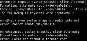
This week I encountered this error for the first time in the years I’m working with JunOS now. Last week I installed two SRX’s at a remote datacenter location in NJ, US. All working fine and once back in my home country I added some monitoring checks to the devices and thought, well lets sync the JunOS alternate partition with the primary. This went just fine:

onno@net> show system snapshot media internal
Information for snapshot on       internal (/dev/da0s1a) (backup)
Creation date: Aug 29 13:54:23 2015
JUNOS version on snapshot:
junos  : 12.1X44-D35.5-domestic
Information for snapshot on       internal (/dev/da0s2a) (primary)
Creation date: Apr 7 13:29:14 2016
JUNOS version on snapshot:
junos  : 12.1X46-D40.2-domestic

onno@net> request system snapshot slice alternate
Formatting alternate root (/dev/da0s1a)…
Copying ‘/dev/da0s2a’ to ‘/dev/da0s1a’ .. (this may take a few minutes)
The following filesystems were archived: /

Then I wanted to double check it both partitions contained the same version, and then I got the error:

onno@net> show system snapshot media internal
error: cannot mount /dev/da0s1a

Eehhh .. wait .. what? That’s not something you want to see on a SRX more than 6000km away. (this is a location with, for now, single internet connection)
So I retried the request snapshot command, without success:

onno@net> request system snapshot slice alternate
Formatting alternate root (/dev/da0s1a)…
error: Could not format alternate root

After digging around I found similar issues on EX’s which were cause by the backup partition still mounted. However I didn’t find the /dev/da0s1a mounted, but did find the following:

onno@net> start shell
% mount
(snip)
/dev/altroot on /altroot (ufs, local, noatime, soft-updates)
(snip)

Solution

Looking at the other SRX, there was no /dev/altroot mounted. So I just unmounted it, and ran the same commands again. Now there’s no error and all fine:

onno@net> start shell
% su –
Password:
root@net% umount /altroot
root@net% exit
logout
% exit
exit
onno@net> request system snapshot slice alternate
Formatting alternate root (/dev/da0s1a)…
Copying ‘/dev/da0s2a’ to ‘/dev/da0s1a’ .. (this may take a few minutes)
The following filesystems were archived: /

onno@net> show system snapshot media internal
Information for snapshot on       internal (/dev/da0s1a) (backup)
Creation date: Apr 15 07:30:11 2016
JUNOS version on snapshot:
junos  : 12.1X46-D40.2-domestic
Information for snapshot on       internal (/dev/da0s2a) (primary)
Creation date: Apr 7 13:29:14 2016
JUNOS version on snapshot:
junos  : 12.1X46-D40.2-domestic

Posted in Juniper | Tagged , , , , , , | 19 Comments

vMotion Fails At 14% – with at least one solution

Every found your self with an issue and spending hours trying to find a solution while none of the Google (or bing) search(find)engine results fixed you’re problem? Well I did just this today. Trying to update our VMWare clusters I noticed some VM’s not willing to vMotion to another node and that the task stalled at 14%. With off course the all clarifying error: “Operation timed out” and from Tasks & Events “Cannot migrate <VM> from host X, datastore X to host Y, datastore X”

My solution:
It turns out that, in my case, there was a vmx-***.vswp file left over from a failed DRS migration. During a DRS migration, because the VMX is started at both nodes, each VMX process create a process swap file, with or -1 of -2 in the name. At a successful DRS migration one of the two will be removed.

So when you browse the datastore you’re failing VM is located on, and you open up the folder of the VM, you should see those two vmx-***.vswp files, as presented in the image below. If you only see one file, sorry, than this solution is not the one you’re looking for.
NOTE: There could be also a vswp file for the VM itself! Leave that one alone!

The oldest one is most likely the one you need to delete. You can do this while the VM is running and most of the time just from the DS browser. If you try to delete the wrong one, or when it’s not possible to delete it from the DS browser, you’ll the following error:

If you’re unsure which one to delete, than the only way is to power down the VM and than the file that remains is the one you need to delete.

If you’re unable to delete the file from the file browser, than you need to start SSH daemon on the host on which the VM is registered and then login through SSH. Navigate to the right datastore and folder and delete it from there:
# cd /vmfs/volumes/<datastore_name>
# cd <VM folder>
# ls -lash *.vswp (just to verify the timestamps and locate the right file)
# rm vmx-<VM name>-[1-2].vswp

That’s it, now you should be able to migrate the VM again while it’s running.

Posted in Software, VMWare | Tagged , , , , | 6 Comments

Reset vSphere / ESX root password with host profiles

Ever found yourself breaking your head on a root password for your ESX(i) host, while it’s still manageable through vCenter? Well, I did!

After searching the internet, I found that there are numerous methods of resetting the root password. Even by using a LiveCD! While most are just working fine, the mostly require you to turn off your host. Something I didn’t want to do. Also, vCenter was still able to manage the host in question, so why can’t we just use vCenter?

vCenter has the ability of configuring VMWare hosts with host profiles, and in these profiles we can configure the ‘administrator’, aka root, account. So why not use it? This post will show you how to use it.

Are you unable to use vCenter or host profiles? Maybe these links are useful for you:
http://www.lucd.info/2012/01/15/change-theroot-password-in-hosts-and-host-profiles/
http://vinfrastructure.it/en/2012/04/esxi-how-to-reset-the-root-password/
http://www.bock.nu/blog/reset-root-password-vmware-esxi-4.1

Let’s start with opening the host profiles option in your vSphere client.

Then we choose to create a new profile, name is something like ‘resetPassword’ and select any baseline host.

Now we wait until the creation is completed.

On the left pane select your new host profile and right-click and select edit profile. Then go to security configuration -> administrator password.

Now on the right pane, select ‘configure a fixed administrator password’ from the drop down box and fill-in the new password.

Click OK and right-click your host profile again. Select ‘enable/disable profile configuration’. By default all options are selected. Make sure that everything except “Security configuration” is deselected. This makes sure that only the security configuration is checked and updated, and ignores all other configuration options in the profile. So there’s less to go wrong. ;o)

Now click OK and we’ll start attaching the host of which we want to reset the password. Click ‘Attach Host/Cluster’ and select the right host, click Attach and then OK.

Select the host and first click ‘check compliance’ so we can double check that there are no other issues and we did not forget to disable a portion of the profile. The compliance should be OK.

When there is something wrong, like you forgot to disable portions of the profile, you see something like this, together with the part which is causing the error.

Fix the issue and repeat the compliance check until it’s OK.
Now we’re going to apply the host profile, and make sure again that only the administrator password will be changed.

———————————————————–
NOTE: The host needs to be in maintenance mode before you can apply a host profile. If the host isn’t yet in maintenance mode, you’ll receive this error:


———————————————————–

Click finish and wait for the job to complete.

Voila, the root account of the host has been reconfigured and you should be able to log in again. Now the only thing left is to detach the host from the profile:

Posted in How To, Software, VMWare | Tagged , , , , , , , | 2 Comments

Setup SRX1400 in cluster over layer2 switching network

This post is about my experience of setting up two SRX1400 nodes in a cluster, geographically separated by a layer2 switching network.

The lab setup had to be redundant and spread over two locations. So I updated both SRX’en to JunOS 11.2R4.3, this version supports clustering and redundant fabric and control links.

This post consists of the following topics:
1. Connecting the SRX’s to the switches
2. Configuring the switchports for the fabric, control links and the 2 Gbps traffic links
3. Configuring the cluster
4. Troubleshooting several issues with SRX1400 clustering

I’ll be using not just plain traffic and basic configuration, but I’ll be also using vlan tagging to reduce cabling in the future and will be configuring a routing instance just to be prepared for the future.

Also I’m paying attention to some issues I encountered during my tests. Things you don’t find in the Juniper documentation. ;o) I’m talking about different VLAN’s for control links, and a issue with the current JunOS releases and using T-SFP modules for your control links causing your control links to fail during setup.

So the complete setup will be like below.

Posted in How To, Juniper | Tagged , , , , , , , , , , | Leave a comment

Upcoming: Setup Juniper SA with Tecti MobileID

Coming soon, my blog about setting up a Juniper SA with Tecti MobileID for Authentication and OTP/SMS. I’ll try to complete the page this month. 😀

Ok sorry, please hang on a little longer..

Posted in Hardware, Juniper, Tecti MobileID | Leave a comment